Heat Transfer Division
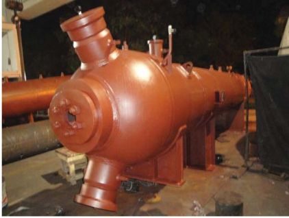
Leading Manufacturers, Exporters and Wholesaler of Steam Surface Condenser, Gland Vent Condenser (Gland Sealing Systems), Steam Condensing System, Feedwater Heaters, Heat Exchanger, Lube Oil Cooler, Dump Condenser and Dump Tubes from Chennai.
| Business Type | Manufacturer, Exporter, Supplier |
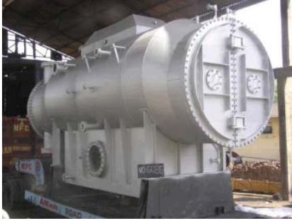
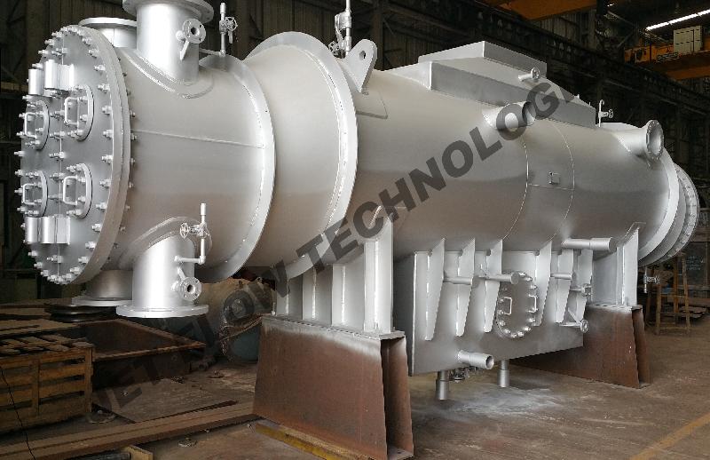
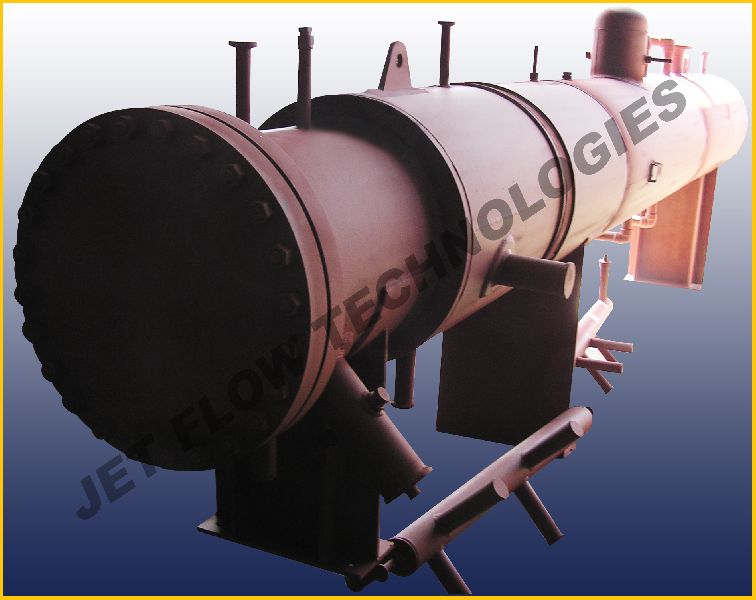
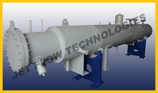
The Steam Surface condenser is a critical component of both the traditional coal fired power plant and the new generation cogeneration and combined cycle power plants.
Main duties of any Surface Condenser are to convert the exhaust steam from its gaseous to its liquid state at certain under atmospheric pressure, and also, to release non-condensable presented in the steam cycle, together with vacuum unit.
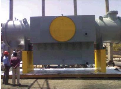
Jet Flow designs and economically sized condenser suitable for smaller turbine ratings under 100 MW. The circular configuration is compact for easy shipping and maintains the level of quality afforded all of our condenser designs.
All of Jet Flow’s Surface Condensers are designed and built to the Heat Exchange Institute latest Standards.We also strive to meet all of our client’s project specific requirements.
Our Condenser design can incorporate enhanced deaeration systems, and or a variety of turbine exhaust options including Axial and Top steam inlet design, which can assist greatly in improving plant layouts. We continually address and refine these and other considerations associated with circular designs where space is at a premium.
Jet Flow Surface Condensers are fabricated in-house state of the art fabrication facilities located in Ahmedabad. All of the fabrication facilities are according toASMEcode and an impeccable reputation for quality fabrication and on time delivery.
Our Surface Condensers feature high overall heat transfer coefficient (which result in smaller heat transfer areas and thus optimal use of the available space) and extremely low oxygen concentrations in the condensate. They are designed to stand up to turbine and steam generator overloads and to variations in cooling water temperature at different times of the year.
Jet Flow Surface Condenser highlights:
- Effective steam distribution within tube nest
- Uniform distribution of heat loading
- Effective collection and removal of noncondensable gases
- Negligible condensate subooling
- Minimized condensate inundation
- Lower velocity fluctuation
- Efficient air cooling section
- Effective de-aeration performance
- One orTwo passes.
- Down Flow, Axial flow or side inlet design.
- 4 to 6 months delivery.
- Available for all type ofTurbines.
Air cooling zone is provided in the coolest part of the condenser, which minimise the carry overof the steam to the ejector vacuum system alongwith the non condensable gases.
Geothermal Steam Condensers:
Jet Flow has many years of experience designing vacuum Condensers with high non-condensable loads. Since Geothermal steam is highly corrosive and contains large amounts of non-condensable gases, the design and fabrication of Geothermal Steam Condensers is radically different than conventional power plant condensers. Special attention to be given on reduced overall heat transfer rates and LMTD due to high amount of non condensable gases, pressure drop, sub-cooling, flow path for venting large volumes and material selection to prevent corrosion. Associated vacuum system is Multi stage Steam Ejectors with direct OR in-direct type inter condensers.
| Business Type | Manufacturer, Exporter, Supplier |
Gland seal systems very important to main and auxiliary turbines.Turbine shafts must exit their casings in order to couple up or connect with the unit that the turbines drive (reduction gears, pumps, etc.) The main and auxiliary gland seal systems enable the turbine to be sealed where the shaft exits the casing; in effect keeping "air out and steam in."
The purpose of gland seal system is to prevent the leakage of air from the atmosphere into turbine casings and prevent the escape of steam from turbine casings into the atmosphere.
The gland sealing system provides low pressure steam to the turbine gland in the final sets of labyrinth packing. This assists the labyrinth packing in sealing the turbine to prevent the entrance of air into the turbine, which would reduce or destroy the vacuum in the associated condenser. Excess pressure (excess gland seal) is removed by the gland seal unloader.
Since there are times when steam escapes from the seals, a gland exhaust system is provided. The gland exhaust system consists of low pressure piping connected to the gland area between the last two outer sets of labyrinths which receives and prevents steam from escaping to the atmosphere. This system collects the steam and directs it to a condenser for further use in the steam plant.
Most steam turbines have a shaft sealing system which uses carbon rings to isolate the rotor assemblies on both ends with steam injected to prevent air in-leakage in to the turbine. The leakage would reduce turbine efficiency and flow into the condenser downstream of the turbine further reducing system efficiency. This gland steam must be removed by an ejector or exhaust fan to prevent it from flowing back into the turbine.
| Business Type | Manufacturer, Exporter, Supplier |
| Click for more Details | |
| Tube Material | Carbon Steel, Stainless Steel, Cu, Nickle Alloys, Titanium, Duplex |
| Tube Sheet | Solid Type Or Cladded |
| Mounting | Mounted Or Prefabricated In Workshop In Common Or Separated Steel Base Frames |
When it comes to the performance of a turbine surface condenser in the operational field of a steam turbine cycle, you need utmost reliability and efficiency. Here’s where Jet Flow’s know how is invaluable. We createcustomise package solutions for each particular customer’s needs.
Our General Scope of Supply:
- Condenser - Circular Condenser having own Flow, Axial flow or side inlet steam entry.
- Turbine to Condenser steam duct, including necessary expansion joints.
- Steam Jet Ejector Vacuum System.
- Flash tank, drain header and Instrument stand pipe.
- Dump Tube.
- Condensate Pump system: Pumps are in vertical or horizontal arrangement; either API 610, ISO 5199 or standard manufacturer pump design.
- Control system: Including level control valves
- pressure and temperature indicators, transmitters and controllers.
- Interconnecting piping with filter, fittings and valves.
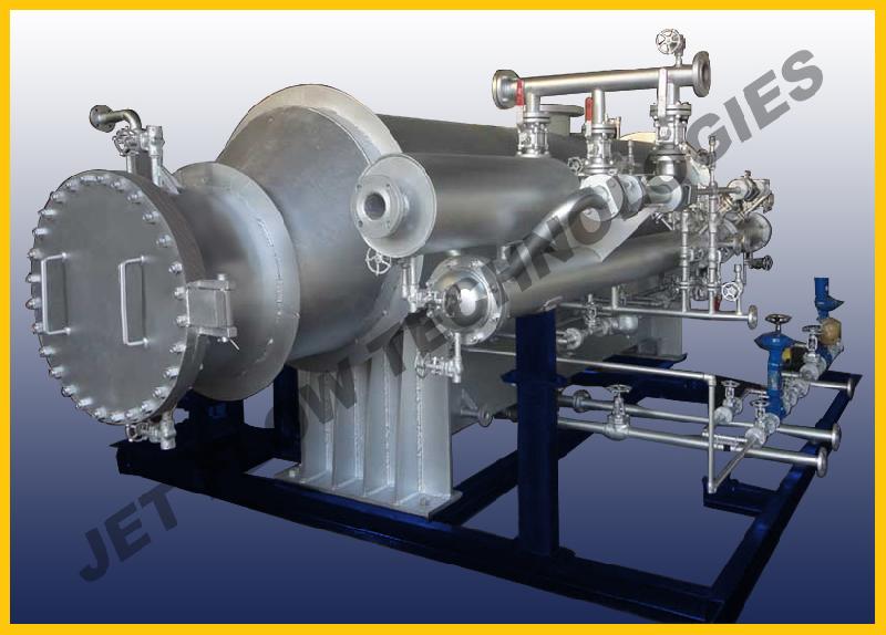
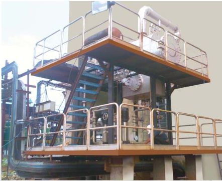
Jet Flow designs, manufactures and supplied overall Condensing System packages involving basic and detail engineering, procurement, testing and delivery. Condensers are manufactured in diverse materials. Tubes are made of carbon steel, stainless steel, Cu and Nickle alloys, Titanium and Duplex. Tube sheets can be solid type or cladded, according to the quality and nature of the cooling water. All components aremounted or prefabricated in our workshop in common or separated steel base frames.
Legend:
- Steam duct and expansion bellow
- Surface condenser.
- Armospheric Relief Valve.
- Condensate extraction Pumps (verticle type)
- Ejector Vacuum system.
- Level Control valves.
- Flash tank.
- Interconnecting piping.
- Normal Level Control valve station
- CEP Minimum recirculation control valve station.
| Business Type | Manufacturer, Exporter, Supplier |
The needs of the power generation industry include year-in and year-out reliability, optimum performance for maximum efficiency, and absolute on-time delivery to meet plant outage schedules.
All of the Jet Flow Feed Water Boiler Heaters are designed in accordance with HEI standards, TEMA and ASME codes. Jet Flow uses state-of-the art computer programs to perform the thermalhydraulic and mechanical design of each Feed Water Heater we fabricate.
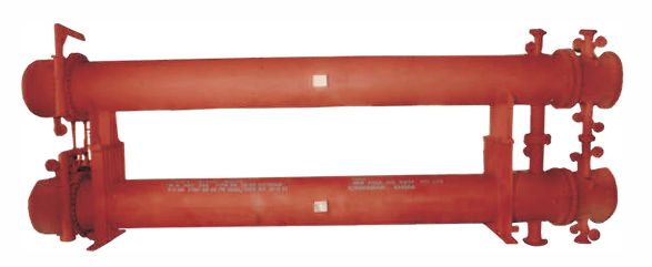
Jet Flow designs and manufactures both Low Pressure (LP) and High Pressure (HP) feed water heaters which may be installed either vertically or horizontally, depending on the plant design requirements.
Each Jet Flow LP / HP Feed Water Heater will contain from one to three separate heat transfer areas of zones including the Condensing, De-superheating and Sub-cooling zones. Our heaters can be provided with multiple zones within the shell side:
- Condensing Zone : Included in all heaters,steam is condensedin this zone and non-condensable gases are removed.
- Drain Cooling Zone : Reduces temperature of drains leaving the condensing zone to below the saturation temperature. Jet Flow is able to provide both fullflow and partial flow drain cooling zones to meet specific plant requirements. DC zones can be applied in any horizontal or verticle heater as needed to meet plant requirements.
- Desuperheater Zone : Floating design and shielding at the tubesheet minimise thermal stresses. All operating cases are analysed to ensure wet wall conditions are prevented. DSH zones can be applied any horizontal or verticle heater as needed to meet plant requirements.
- Jet Flow’s engineers are always available to assist you in determining those design parameters and how they will impact performance in your power plant.
- Jet Flow understand the unique needs of the power generation industry and provides it feed water heaters that withstand years of rigorous service.
Jet Flow Feed Water Heaters are designed for specific thermal conditions and manufactured for a singular purpose. Whether it be sophisticated designs involving extreme superheat, abnormal flow conditions or dissipation of high energy fluids.
In addition, Jet Flow provides innovative and practical concepts to ensure peak heater performance from installation to testing through full or part load operation. We offer a multitude of design configuration for de-super heater and drain cooler zones as well as the latest channel closure techniques.
All shell & tube heat exchangers, irrespective of the type of service for which they were designed, must withstand severe service conditions. The service life of feed water heaters, however, is one of the toughest because of the longevity and reliability factors inherent in power plant equipment designs. Jet Flow thorough understanding of these factors enhances its ability to communicate clearly with power design engineers. Jet Flow designs enable power engineers to anticipate maximum efficiency from the turbine extraction steam in preheating the boiler feed water.
Scope offering:
- Jet Flow low pressure boiler feed water heaters can be provided in any orientation and contain multiple shell side zones as required to meet the need of the specific plant application. Standard tube material for Jet Flow Feed water heaters is corrosion and erosion resistant austenitic stainless steel. Tubes are expanded in the tubesheet as a standard, but can be welded when required.
- Jet Flow boiler feedwater heaters are manufactured according to the strict quality standards. Testing and certification by the responsible authorities including IBR are performed in the production facility.
- Along with the heaters, Safety Relief Valves, Thermal Relief Valve, Level Instruments and Gauges can be supplied.
| Business Type | Manufacturer, Exporter, Supplier |
| Application | Industrial Heat Exchanger |
| Country of Origin | India |
| Tube Sheet Thickness | Up To 150mm |
| Speciality | Available Up To Surface Area Of 2750 M2 ,Highest Sealing Through Precision Tube Expander. |
| Material Of Construction | Stainless Steel,Carbon Steel,Alloy Steel,ADM-Brass,Graphite,Other Exotic Materials |
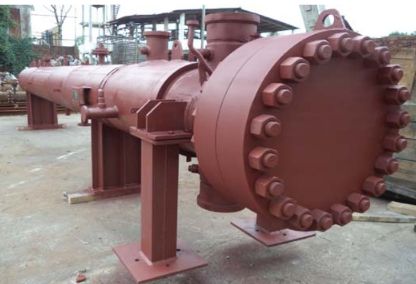
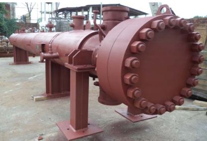
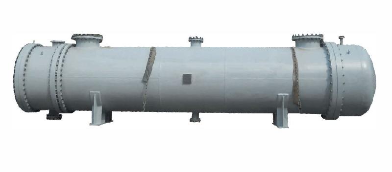
A heat exchanger is a device built for efficient heat transfer from one medium to another, whether the media are separated by a solid wall so that they never mix, or the media are in direct contact. Product Range - Fixed Tube Sheet Floating Head U Tube Double Pipe Kettle Features - Heat Exchanger is available up to Surface area of 2750 m2 Tube sheet thickness up to 150mm Highest sealing get through electronically controlled precision tube expander. Design Standard and codes - ASME Sec VIII with and without "U" Stamp TEMA ISS 4503 ISS 2825 HEI PED AD MERK Material of Construction - Stainless Steel Carbon Steel Alloy Steel ADM-Brass Graphite Other Exotic Materials
| Business Type | Manufacturer, Exporter, Supplier |
| Click for more Details |
Lub oil reduces friction between moving mechanical parts and also removes heat from the components.
As a result, the oil becomes hot. This heat is removed from the lube oil by a cooler to prevent both breakdown of the oil and damage to the mechanical components it serves.
The lube oil temperature must be maintained within a specific operating band to ensure optimum equipment performance.
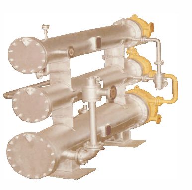
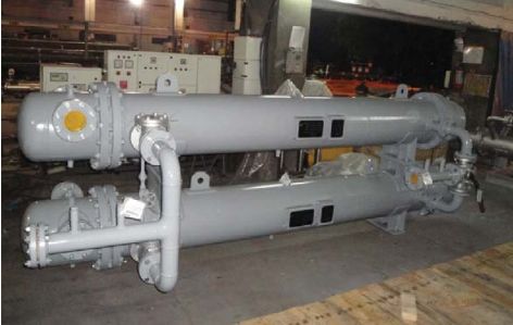
Lube oil coolers are designed based on the customer specifications. Designs are available as single coolers or duplex coolers with change over valves.
Duplex coolers can be supplied either in standard Horizontal design or vertical design if space is constrains.
| Business Type | Manufacturer, Exporter, Supplier |
Dump Condensers are used to recover large amounts of steam that may otherwise be vented to the atmosphere. During fluctuating steam loads, turbine trip off, turbine start-up,or bypass, the excess steam that would ordinarily be vented can be diverted to a dump condenser. Dump Condensers may also be used for process plants when upset demand conditions occur.
A dump condenser is required when the steam consumption needs to be drastically reduced in a very short period of time and when the boiler cannot follow this variation.
Features :
- Water-cooled Dump Condensers
- Fabrication and design typically to Heat Exchange Institute
- Standard (HEI), ASME Code, and can include TEMA, Seismic
- Codes, and other specifications.
Designs to eliminate excessive vibrations and water hammer Standard materials are carbon steel with stainless steel tubes. Special materials are available for severe duty or other applications.
Dump Condenser can be furnished as a system which may consist of Steam Pressure/Temperature Reducing Station and Condensate Recovery System which includes Level Controls, Condensate Pumps, and Electrical Control Panel for automatic
operation.
| Business Type | Manufacturer, Exporter, Supplier |
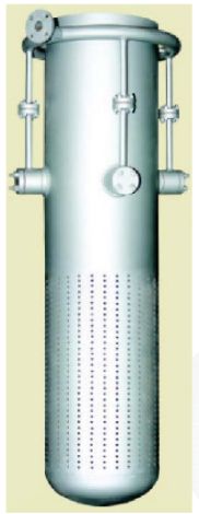
Dump Tubes are an important part of a system discharging in a condenser. These devices are primarily deployed so as to minimize the size of the bypass valve outlet where the specific volume of steam dramatically increases at low or sub-atmospheric pressures.
These dump tubes are normally fitted into the condenser inlet duct and are carefully designed to achieve the final pressure reduction stage and allow the steam to expand and cool prior to entering the turbine exhaust or condenser.
It is recommended to ensure that the Ddump Tube is designed properly with respect to size, shape and profile so as to a void interference with the turbine exhaust steam path under normal turbine operation. The arrangement and the size of the holes in the dump tube are selected so as to minimize noise generation and direct the steam path away from the duct walls and towards the condenser inlet depending upon the installation.
Depending upon the installation, the arrangement of the holes are selected. In case the Dump Tube is installed in the condenser then the arrangement of the holes are drilled in two 90 degree sectors.
This does not allow the steam to go up the turbine exhaust or directly down on to the tubes in the condenser.
In case the dump tube is installed in the turbine exhaust then the holes are drilled around the complete circumference i.e.360 degrees.
Operating philosophy:
- The cooling water required to bring down the temperature is sprayed in the valve or in the dump tube. No water is sprayed in the Condenser. The amount of cooling water quantity is calculated by heat balance calculation. Feed forward logarithm is used in the Distribution Control System
- Inlet steam pressure, temperature, and the position of the valve give the low rate of steam via the valve characteristics. The required spray water quantity is calculated as the algorithm has pre-programmed steam tables and is compared via the FT Flow transmitter installed in the spray water line or position feed back transmitter.
- The result is the control signal given to the valve positioner of the spray water valve. The pressure transmitter installed on the dump tube measures the steam pressure in the dump tube. Since the dump tube is a fixed orifice, the signal from the pressure transmitter indicates the flow through the dump tube.
- Since the dump tube is a fixed orifice, the signal from the pressure transmitter indicates the flow through the dump tube.


